Ein 3D-gedruckter Jig ist nur so gut wie sein Design. Sie können das perfekte FDM-Material auswählen, einen Drucker auf Industriegrad verwenden und enden trotzdem mit einer Spannvorrichtung, die unter Last verbiegt, in einer Woche abnutzt oder Teile 2 mm später als spezifiziert positioniert. Der Unterschied zwischen einem funktionierenden Produktionswerkzeug und einem fehlgeschlagenen Versuch kommt auf Design-Entscheidungen an: Wandstärke, Druck-Orientierung, Füll-Strategie, Toleranzgebung und Integrations-Merkmale.
Dieser Leitfaden behandelt die praktischen Ingenieursregeln für das Design von FDM-Jigs und Spannvorrichtungen, die auf dem Fabrikfloor tatsächlich funktionieren. Keine Theorie-Vorträge – nur praktische Richtlinien, unterstützt durch Produktionserfahrung.
Regel 1: Wandstärke – Dicker als Sie denken
Der häufigste Anfänger-Fehler ist das Design von FDM-Spannvorrichtungen mit dünnen Wänden. Was in CAD gut aussieht, scheitert unter echten Spannkräften und wiederholter Handhabung in der echten Welt.
Minimum-Wandstärke: 1,5 mm für jedes strukturelle Merkmal. Dies gewährleistet ordnungsgemäße Schicht-Bindung, Druckbarkeit und minimale Last-Kapazität.
Empfohlen für Produktions-Jigs: 2–3 mm für Last-tragende Wände, Datum-Oberflächen und Spann-Bereiche. Dickere Wände verteilen Spannkräfte über mehr Material, reduzieren lokalisierte Verformung.
Hochbelastungs-Zonen: 3–4 mm. Bereiche direkt unter Spannpolstern, um Metall-Einsätze oder bei Snap-Fit-Basen brauchen zusätzliches Material, um die konzentrierten Lasten, die sie erfahren, zu widerstehen.
Eine gute Faustregel: Falls die Wandstärke 1 mm im Spritzguss wäre, machen Sie 2 mm in FDM. Die Schicht-verbundene Struktur von FDM-Teilen braucht mehr Material, um äquivalente Zwischen-Schicht-Festigkeit zu erreichen.
Regel 2: Druck-Orientierung bestimmt Festigkeit
FDM-Teile sind anisotrop – signifikant schwächer zwischen Schichten (Z-Richtung) als entlang der Schicht-Ebene (XY-Richtung). Dies ist kein unbedeutender Effekt: Zugfestigkeit in der Z-Richtung ist typischerweise 50–70 % der XY-Festigkeit, je nach Material.
Für Jigs und Spannvorrichtungen bedeutet dies, dass Print-Orientierung eine strukturelle Entscheidung ist, nicht nur eine Druck-Komfort-Auswahl.
Orientierungs-Strategie
Identifizieren Sie die primäre Last-Richtung. Widersteht der Jig Spannkräften? Biegungslasten? Zugzug aus Werkstück-Extraktion? Erstellen Sie die Last-Wege durch Ihre Spannvorrichtung, bevor Sie sich für Orientierung entscheiden.
Richten Sie Schichten senkrecht zur primären Last aus. Falls Ihre Spannvorrichtung eine Druck-Spannkraft von oben absorbiert, orientieren Sie das Teil so, dass Schichten vertikal stapeln – Druck-Lasten sind die am wenigsten beeinflußten durch Schicht-Grenzen.
Niemals unter reiner Spannung über Schichten laden. Ein Spann-Arm, der zwischen Schichten auseinanderreißt, scheitert bei 50–60 % der publikuzierten Material-Zugfestigkeit. Drehen Sie das Teil 90°, damit die Spannung entlang der Schicht-Ebene verläuft.
Allgemeine Orientierungen für Jig-Typen
Jig-TypBeste OrientierungWarumBohrführe (vertikal Bohren)Flach auf DruckplatteBohr-Kräfte komprimieren Schichten, stärkste KonfigurationMontage-Positionierungs-SpannvorrichtungFlach auf DruckplatteDatum-Oberflächen drucken unten (flachste Oberfläche)Spann-Hebel/Umschalthebel-Achse parallel zu XYBiegungs-Festigkeit maximiert entlang Schicht-EbeneHandheld Inspektions-LehreTallest-Merkmal vertikalMinimiert Stützen, hält Genauigkeit auf Lehren-FlächenKabel-Routing-ClipClip-Offnung horizontalSnap-Merkmal-Festigkeit maximiert
Wenn Orientierung nicht genügt
Für komplexe Spannvorrichtungen mit mehrrichtungs-Lasten, betrachten Sie die Aufteilung des Designs in zwei oder drei Teile, jeden in seiner optimalen Orientierung gedruckt, dann mit Epoxy oder mechanischen Befestigungen verbunden. Dieser Ansatz gibt jedem Abschnitt maximale Festigkeit in seiner kritischen Last-Richtung.
Regel 3: Füllung – Nicht zu viel, nicht zu wenig
Füll-Prozentanteil direkt beeinflußt Festigkeit, Gewicht, Druck-Zeit und Kosten. Die optimale Füllung hängt von Ihrer Spannvorrichtungs-Last-Fall ab.
15–20 % Füllung: Leicht, nicht-kritische Anwendungen (Verpackungs-Tabletts, Organisierungs-Nester, Visualisierungs-Prototypen). Schnell zu drucken, minimale Material-Kosten.
30–40 % Füllung: Der süße Punkt für die meisten Produktions-Jigs. Bietet gutes Festigkeit-zu-Gewicht-Verhältnis für moderate Spannkräfte und wiederholte Handhabung.
50–70 % Füllung: Hochbelastungs-Produktions-Spannvorrichtungen, Bohrführe und Werkzeuge, die Schlag oder Vibration absorbieren. Signifikant stärker als 30 % Füllung mit moderater Druck-Zeit-Erhöhung.
100 % Füllung: Fast nie notwendig. Die Festigkeits-Erhöhung von 70 % bis 100 % Füllung ist minimal (sinkende Renditen), aber Druck-Zeit und Material-Kosten steigen erheblich. Nutze 100 % nur für sehr kleine, stark belastete Merkmale.
Füll-Muster-Auswahl
Gitter oder Linien: Schnell zu drucken, ausreichend für die meisten Anwendungen. Leichte direktionale Schwäche.
Gyroid: Am besten für isotrope Festigkeit (gleich in allen Richtungen). Leicht längere Druck-Zeit, aber eliminiert Füll-Orientierungs-Abhängigkeit.
Waben: Ausgezeichnet für Last-Verteilung Über Oberflächen. Gute Auswahl für Spannvorrichtungen mit verteiltem Spannungsdruck.
Für Produktions-Werkzeugung ist Gyroid bei 30–40 % Füllung ein zuverlässiger Standard, der über die meisten Anwendungen funktioniert.
Regel 4: Toleranzen – Planung für Wirklichkeit, nicht CAD-Perfektion
FDM ist nicht CNC-Bearbeitung. Teile verlassen den Drucker innerhalb von ±0,3–0,5 mm der nominalen Dimensionen, nicht ±0,025 mm. Das Design von Spannvorrichtungen, die engere Toleranzen brauchen, ohne Nachbearbeitung ist ein Fehler-Auslöser.
Praktische Toleranz-Richtlinien
Nicht-kritische Merkmale (Freiraum-Löcher, Zugangs-Öffnungen): Design zu ±0,5–1,0 mm. Großzügiger Freiraum vermeidet Probleme.
Positionierungs-Merkmale (Datum-Oberflächen, Pin-Bohrungen): Design zu ±0,3 mm und Plan für Nachbearbeitung, wenn nötig. Bohr- oder Raub-Löcher zur endgültigen Größe. Schleifen oder Maschinen-Datum-Oberflächen flach.
Präzisions-Merkmale (Lehren-Oberflächen, Sensor-Sitze): Design 0,1–0,2 mm Oversize und beenden zur Spezifikation durch Raub, Bohren oder leichte Bearbeitung. Eine 25 € gedruckte Spannvorrichtung mit zwei geraubten Positiv-Löchern erreicht die gleiche Präzision wie ein 500 € bearbeitetes Teil.
Shrinkage-Kompensation
ABS schrumpft 0,5–0,8 % während des Kühlens. PETG schrumpft 0,1–0,3 %. Nylon-Materialien schrumpfen variabel je nach Feuchtigkeitsgehalt. Für große Spannvorrichtungen (200+ mm) ist dieser Schrumpf meßbar und muss im Design oder in den Slicer-Einstellungen kompensiert werden.
Pro-Tipp: Drucken Sie einen Kalibrierungs-Würfel (50×50×50 mm) in Ihrem ausgewählten Material auf Ihrem spezifischen Drucker und messen Sie ihn. Nutzen Sie den gemessenen Schrumpf-Prozentanteil als Skalierungsfaktor in Ihrem Slicer. Dieser einfache Schritt eliminiert die meisten dimensionalen Genauigkeits-Beschwerden.
Baugruppen-Toleranz Stack-Up
Mehrteil-Spannvorrichtungen sammeln Toleranzen. Jedes Teil trägt ±0,3–0,5 mm Variation bei, daher kann eine dreibeil-Baugruppe um ±0,9–1,5 mm beim Datum am weitesten vom Ursprung entfernt sein. Machen Sie das abschwacher, indem Sie Dolen-Pins oder Positionierungs-Merkmale verwenden, um Teile während der Baugruppe zu registrieren, und Design mit Slip-Fits (0,05–0,1 mm Freiraum) an Registrierungs-Punkten.
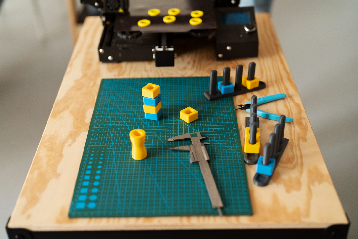
Regel 5: Metall-Einsätze – Der Hybrid-Ansatz
Reine FDM-Spannvorrichtungen verarbeiten die meisten Werkzeug-Anwendungen, aber einige Merkmale profitieren von Metall-Verstärkung. Gewinde-Einsätze, Dolen-Pins und Buchsen addieren Haltbarkeit und Präzision genau, wo notwendig, bei minimalen Kosten.
Wärme-gesetzte Einsätze (Empfohlen)
Wärme-gesetzte Messing-Einsätze sind der Gold-Standard für das Hinzufügen von Gewinden zu FDM-Teilen. Ein Löteisen oder dediziertes Installations-Werkzeug heißt den Einsatz auf 200–250°C auf und drückt es in ein pre-entworfenes Loch. Das umgebende Kunststoff schmelzt und reformiert sich um die gekerbte Außenseite des Einsatzes, was eine starke, permanente Bindung schafft.
Design-Regeln für Wärme-gesetzte Einsätze:
- Loch-Durchmesser: Abstimmungs-Hersteller-Empfehlung (typisch 0,1–0,2 mm kleiner als Einsatz-OD)
- Boss-Wandstärke: Minimum 1,5 mm Kunststoff um den Einsatz
- Boss-Tiefe: Erweitern Sie 2–3 mm über den Einsatz, um Bottom-Out zu verhindern
- Auszugs-Widerstand: 50–200 N für M4-Einsätze in ABS (ausreichend für Hand-angespannte Spannungen)
Kosten pro Einsatz: 0,20–0,50 €. Installations-Zeit: 30–60 Sekunden jeweils.
Dolen-Pins für Präzisions-Positionierung
Presse-gepasste Stahl-Dolen-Pins bieten Positionierungs-Genauigkeit, die FDM allein nicht erreichen kann. Design das FDM-Loch 0,1 mm untersize, dann raub zur endgültigen Durchmesser nach dem Druck. Das Ergebnis: ±0,025 mm Positionierungs-Genauigkeit auf einer FDM-Spannvorrichtung.
Buchsen für Verschleiß-Widerstand
Bronze- oder Stahl-Buchsen an Hochverschleiß-Punkten (Bohr-führungs-Bohrungen, Gleit-Kontakt-Oberflächen) erweitern die Spannvorrichtungs-Lebensdauer von Hunderten von Zyklen zu Zehntausenden. Design die Bohrung leicht untersize und press- oder epoxy-Buchsen an Ort und Stelle.
Der 3D-gedruckt-vs-CNC-Vergleich erforscht Hybrid-Ansätze im Detail.
Regel 6: Ergonomisches Design für handheld Werkzeuge
Ein signifikanter Anteil der Fabrik-Jigs sind handheld – Bohrführe, Inspektions-Lehren, Montage-Hilfen, gehalten von einem Bediener Hunderte Male pro Schicht. Ergonomie beeinflußt direkt Produktivität, Qualität und Arbeiter-Sicherheit.
Gewichts-Ziel
FDMs größte Ergonomie-Vorteil ist Gewichts-Reduktion. Ein typisches Aluminium-Werkzeug wiegt 2–5× mehr als das FDM-Äquivalent. Ziel 150–400 g für handheld Werkzeuge. Über 500 g, Bediener erfahren Ermüdung über eine ganze Schicht.
General Motors' Arlington-Anlage ersetzte 10–40 lbs Aluminium-Handwerkzeuge durch 3 lbs Nylon-Kohlefaser-Äquivalente. Bediener-Ermüdung sank, und die Werkzeuge waren leichter, sich in engen Montage-Positionen zu maneuvrieren.
Griff-Design
- Durchmesser: 28–35 mm für komfortablen Erwachsenen-Griff
- Länge: 80–120 mm Minimum für sichere Zwei-Hand-Operation
- Textur: Führen Sie Kornzeichnung oder Rippenmuster hinzu – FDM-Oberflächen sind natürlich glatt und können mit behandschuhten Händen rutschig sein
- Konturen: FDM erlaubt organische Formen, die CNC nicht wirtschaftlich produzieren kann. Design-Finger-Ruhestätten, Daumen-Einspannungen und Palm-Konturen, die der natürlichen Hand-Position für Ihre spezifische Operation entsprechen
Ein-Hand-Bedienung
Design-Jigs für Ein-Hand-Bedienung, wo immer möglich. Dies gibt dem Bediener's andere Hand frei für Teile-Handhabung, verbessert Zyklus-Zeit und reduziert die Versuchung, das Werkzeug in einer unkontrollierten Position zu setzen.
Regel 7: Poka-Yoke (Fehler-Absicherung) Design
3D-Druck's Design-Freiheit erlaubt Poka-Yoke (Fehler-Absicherung) Merkmale, die kostspielig wären zu bearbeiten. Dies ist einer von FDM-Werkzeugs am meisten untergeschätzten Vorteil.
Machen Sie falsche Baugruppe unmöglich
Asymmetrische Positional-Pins: Platzieren Sie Positional-Pins in einem nicht-symmetrischen Muster, daher das Werkstück kann nur in der korrekten Orientierung installiert werden. Ein Muster von 3 mm + 5 mm + 8 mm Pins in einer dreieckigen Anordnung eliminiert 180°-Drehungs-Fehler.
Gesperrte Höhlungen: Design die Jig-Höhlung, um genau die Werkstück-Umriße zu passen, einschließlich asymmetrischer Merkmale. Falsche Teile können buchstäblich nicht passen.
Höhen-Stopps: Verstellbare vertikale Stopps bestätigen das Teil ist voll eingesetzt. Ein Teil, das zu groß ist oder falsch positioniert, wird den Stopp nicht lichten.
Bieten Sie Rückmeldung
Snap-Engagement: Design-Spannungsverfahren mit dem Audible-Klick bei voller Einbindung. Bediener weiß, dass das Teil ohne visuelle Verifikation gesichert ist.
Farb-Kodierung: Drucken Sie verschiedene Abschnitte in verschiedenen farbigen Filamenten (falls Ihr Drucker Multi-Material unterstützt) oder malen Sie Zonen, um Teile-Platzierungs-Standorte zu zeigen.
Visuelle Indikatoren: Design einen Tab oder eine Flagge, die nur sichtbar ist, wenn der Spannhebel voll geschlossen ist. Offene Spannhebel = rote Anzeige sichtbar. Geschlossene Spannhebel = grüne Anzeige sichtbar.
Verhindern Sie Schäden
Kraft-Begrenzer: Design Snap-Fit Spannhebel mit definierter maximaler Verformung. Über-Spannen (was das Werkstück beschädigen könnte) bottoms physisch den Spannhebel, bevor excessive Kraft entwickelt.
Zwei-Schritt-Freigabe: Erfordern Sie, dass Sie einen Button drücken plus einen Hebel drehen, um das Werkstück freizugeben. Dies verhühtet verursachte Freigabe während Handhabung oder Transport.
Regel 8: Design für Druckbarkeit
Ein Jig, der in der Theorie perfekt funktioniert, aber nicht zuverlässig druckt, ist nutzlos. Design mit FDM-Prozess-Beschränkungen im Sinn.
Überhänge und Stützen
FDM verarbeitet Überhänge bis zu 45° von vertikal ohne Stütz-Strukturen. Darüber hinaus sind Stützen notwendig – und Stützen verlassen Oberflächen-Marken, die die Datum-Genauigkeit beeinflussen könnten.
Strategie: Orientieren Sie das Teil, daher kritische Oberflächen (Datum-Flächen, Positionierungs-Oberflächen) sind entweder auf der Druckplatte (flachste Oberfläche) oder auf selbststützen Winkeln. Platzieren Sie Stützen nur auf nicht-kritischen Oberflächen.
Überbruckungs
Horizontale Spannweiten bis zu 10 mm Überbrücken ohne Stütze auf den meisten Druckern. Über 10 mm, erwarten Sie Durchhängen. Für längere horizontale Merkmale, fügen Sie eine leichte Welle (0,5–1 mm Anstieg über die Spannweite) hinzu oder design in einer Stütz-Rippe, die nach dem Drucken entfernt werden kann.
Vermeiden Sie gefangene Volumen
Geschlossene Höhlungen fängen Stütz-Material, das nicht entfernt werden kann. Design alle internen Merkmale mit mindestens einer Zugangs-Öffnung für Stütz-Entfernung oder Inspektion.
Minimieren Sie große flache Oberflächen
Große flache Oberflächen, die zur Druckplatte parallel sind, sind wölbungs-anfällig (besonders in ABS). Fügen Sie Rippen, Runde oder Gittermusters auf der Unterseite hinzu, um thermischen Stress zu brechen.
Allgemeine Design-Fehler (und wie Sie sie vermeiden)
FehlerFolgeLösungWände unter 1,2 mmDruck-Fehler oder strukturelle SchwächeMinimum 1,5 mm, 2–3 mm für beladene BereicheLaden über Schichten in SpannungVoreiliger Fehler bei 50–60 % der bewerteten SterkeDrehen Sie Orientierung 90°, um Last mit Schicht-Ebene auszurichten100 % Füllung überallExzessive Druck-Zeit und Kosten mit minimalen Festigkeits-VorteilNutzen Sie 30–50 % mit Gyroid-Muster für die meisten MerkmaleLöcher gedruckt zum exakten Bolzen-DurchmesserLöcher schrumpfen 0,3–0,5 mm; Bolzen passen nichtOversize-Löcher um 0,3–0,5 mm oder Raub nach dem DruckenScharfe interne EckenStress-Konzentration und Riss-InitiierungFügen Sie 0,5–1 mm Füll-Radien auf alle internen Ecken hinzuKeine Shrinkage-Kompensation auf großen TeilenTeile 0,5–2 mm untersize auf 200+ mm FunktionKalibrieren Sie Drucker, nutzen Sie Skalierungs-Faktor in SlicerDesign als einzelnes monolithisches TeilSuboptimale Orientierungs-Kompromisse Festigkeit Spalten Sie in Teile auf, drucken Sie jeweils in optimaler Orientierung, verbinden Sie sieIgnorieren Sie NachbearbeitungKritische Oberflächen außerhalb der ToleranzPlanieren Sie für Raub, Schliff oder Maschinen-Datum-Merkmale
Design-Checkliste: Bevor Sie Druck hängen
Nutzen Sie diese Checkliste für jede Spannvorrichtungs-Design, bevor Sie ihn zum Drucker schicken:
Strukturell:
- [ ] Minimum 1,5 mm Wände (2–3 mm für beladene Bereiche)
- [ ] Primäre Lasten auf XY-Schicht-Ebene ausgerichtet
- [ ] Füllung 30–50 % mit Gyroid- oder Gitter-Muster
- [ ] Füll-Radien ≥0,5 mm auf alle internen Ecken
Dimensional:
- [ ] Kritische Löcher Oversize 0,2–0,5 mm für Post-Fertigstellung
- [ ] Datum-Oberflächen zuverlässig für Schleifen/Bearbeitung
- [ ] Shrinkage-Kompensation für Teile >150 mm angewendet
- [ ] Mehrteil-Baugruppen-Toleranz Stack-Up berechnet
Integration:
- [ ] Wärme-gesetzte Einsatz-Boss-Größen pro Hersteller-Spezifikation
- [ ] Dolen-Pin-Löcher für Ream-zu-Fit entworfen
- [ ] Buchsen für Hochverschleiß-Bohr-/Kontakt-Punkte spezifiziert
- [ ] Snap-Fit-Merkmale zuerst auf Prototyp getestet
Benutzerfreundlichkeit:
- [ ] Poka-Yoke-Merkmale verhindern falsche Orientierung
- [ ] Gewicht unter 500 g für handheld Werkzeuge
- [ ] Griff-Durchmesser 28–35 mm mit strukturierter Oberfläche
- [ ] Visuelle Indikatoren für Spannhebel-Zustand
Druckbarkeit:
- [ ] Stütz-Strukturen nur auf nicht-kritischen Oberflächen
- [ ] Keine gefangenen internen Volumen
- [ ] Überhänge ≤45° wo möglich
- [ ] Große flache Oberflächen gerippet oder gittergebunden
Schlussfolgerung: Design ist der Multiplikator
Die Kosten-Einsparungen von FDM-Werkzeugen sind gut dokumentiert – 70–90 % Reduktionen gegenüber CNC-Bearbeitung. Aber diese Einsparungen nur materialisieren, wenn Spannvorrichtungen für die Technologie entworfen sind. Ein schlecht entworfener FDM-Jig, der Neudesign und Nochmals-Druck drei Mal braucht, spart trotzdem Geld gegen CNC, aber ein gut entworfener Jig, der beim ersten Druck funktioniert, maximiert Zeit- und Kosten-Einsparungen.
Investieren Sie 30 Minuten in ordnungsgemäße Design-Analyse – Last-Wege, Orientierung, Toleranzen, Einsätze – und Sie können Stunden Iterations-Downstream einsparen.
Brauchen Sie Hilfe, Ihre erste FDM-Spannvorrichtung zu entwerfen? Laden Sie Ihr CAD-Modell auf 3D On Demand hoch und unser Ingenieurs-Team wird Ihr Design überprüfen, Material und Orientierung empfehlen und produktions-bereite Spannvorrichtungen liefern.

Apr 8, 2026
Design during the day, print overnight, test the next morning. A practical workflow for running rapid prototyping iterations at one per day.
Apr 8, 2026
A structured checklist for testing 3D printed prototypes: visual inspection, fit testing, functional validation, and user testing. Get the most out of every iteration.
.webp)


Copyright © 3D On Demand