Apr 8, 2026
In this guide, we walk you through the full process of designing and 3D printing electronic enclosures: from choosing the right wall thickness and snap-fit geometry, to selecting the best printing technology for your stage of development.
Whether you're building a sensor housing for an IoT device, a controller box for a robotics project, or a sleek case for a consumer gadget — this is the practical guide product designers and hardware engineers have been asking for.
Why 3D Print Your Enclosure?
Traditional enclosure manufacturing — injection molding, CNC machining, vacuum forming — requires tooling, setup costs, and lead times measured in weeks. That makes sense at scale. But when you're still iterating on your design, testing component fit, or preparing for a pitch, those timelines and costs are a bottleneck.
A professional 3D print service removes that bottleneck entirely. You upload a STEP or STL file, receive an instant quote, and have a physical enclosure in your hands within days. If the fit isn't right, you adjust your CAD, reorder, and test again — all without touching a mold.
This is especially powerful for hardware startups building MVPs, product teams validating form factor with real users, and engineers who need to test thermal, mechanical, or assembly behavior before committing to production tooling.
Start With Your Internal Components
Before you open your CAD software, gather your internals. The enclosure exists to house and protect components, so start there.
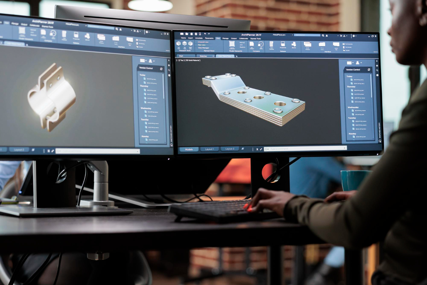
Measure or import the 3D models of your PCB, battery, connectors, display, buttons, and any other internal parts. Pay attention to the connector positions — USB ports, charging ports, antenna placements — because these define where your enclosure needs openings.
Create a layout in your CAD tool where all components are positioned relative to each other. This internal assembly becomes the skeleton around which you'll design the housing.
A few things to account for early on: cable routing paths between components, heat-generating parts that need ventilation or spacing, any parts that the user needs to access (like SD card slots or reset buttons), and mounting points for the PCB using standoffs or clips.
Wall Thickness: The Foundation of a Good Enclosure
Wall thickness is the single most important design decision for a 3D printed enclosure. Too thin and the part will be fragile or warp during printing. Too thick and you waste material, add weight, and increase cost.
Here are the recommended minimums per technology:
FDM (Fused Deposition Modeling): Minimum 1.5mm, recommended 2.0mm. FDM parts have visible layer lines and slightly lower dimensional accuracy, but they're fast and cheap — perfect for early-stage concept enclosures where you're checking component fit and overall proportions.
SLA (Stereolithography): Minimum 1.0mm, recommended 1.5mm. SLA delivers smooth surfaces and fine details, making it ideal for presentation enclosures — the ones you photograph for your website, show to investors, or use in user testing where aesthetics matter.
SLS (Selective Laser Sintering): Minimum 1.0mm, recommended 1.5mm. SLS nylon parts are strong, durable, and have consistent mechanical properties. This is your go-to for functional enclosures that need to survive real-world handling, snap-fit assembly cycles, and drop tests.
MJF (Multi Jet Fusion): Minimum 0.8mm, recommended 1.5mm. Similar mechanical properties to SLS with slightly finer surface detail. Excellent for functional prototypes and small production batches.
As a general rule, add 0.5mm clearance around any internal component to account for printing tolerances, and 1.0mm if you're using FDM.
Designing Snap-Fits and Assembly Features
Most enclosures need to open and close — for assembly, battery replacement, or maintenance. Snap-fits are the most popular approach for 3D printed enclosures because they eliminate the need for screws and allow tool-free assembly.
Cantilever snap-fits are the most common type. A flexible arm with a hook on the end deflects during assembly and snaps into a matching groove. For 3D printed parts, the key design parameters are the beam length (longer beams deflect more easily and reduce stress), the overhang depth (typically 0.5–1.0mm for printed parts), and the beam thickness (thinner beams are more flexible but weaker).
For SLS and MJF nylon, cantilever snap-fits work exceptionally well because nylon has natural flex and fatigue resistance. You can design snap-fits that survive hundreds of open/close cycles. For SLA resin, be more conservative — resin is stiffer and more brittle, so use longer beams with less overhang.
For FDM prototypes where you're just checking fit, you can even skip snap-fits entirely and use a simple friction fit or tape. Don't over-engineer your first iteration.
Other assembly options worth considering: threaded brass inserts that you heat-press into FDM or SLS parts for screw connections, living hinges in SLS nylon for flip-open lids, tongue-and-groove joints for alignment without fasteners, and adhesive bonding for permanent assemblies.
Ventilation and Thermal Management
If your electronics generate heat — and most do — your enclosure needs a thermal management strategy.
The simplest approach is ventilation slots or holes. Place them near heat-generating components (processors, voltage regulators, motor drivers) and ideally create an airflow path with inlet openings at the bottom and outlet openings at the top, since hot air rises naturally.
Design ventilation slots at least 1.5mm wide for FDM and 1.0mm for SLA/SLS to ensure they print cleanly. A grid or louvre pattern provides ventilation while maintaining structural integrity and keeping debris out.
For more demanding thermal applications, consider designing internal mounting features that press heat-generating components against the enclosure wall for conductive cooling, or leaving open areas in the enclosure for aftermarket heatsinks.
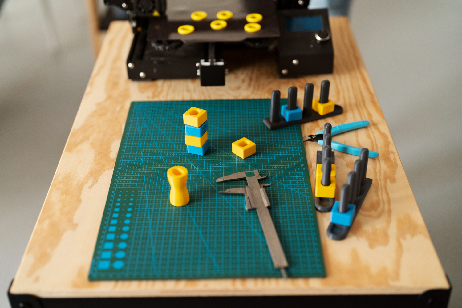
With 3D print on demand, you can quickly test multiple ventilation strategies. Print three variations, run thermal tests with your electronics running inside, and measure which approach keeps temperatures within spec. This kind of rapid experimentation would take weeks with traditional manufacturing — with an on-demand 3D printing service, you can do it in days.
Tolerances and Fit: Getting It Right
Dimensional accuracy varies by printing technology, and this directly affects how well your enclosure fits together and how precisely it mates with internal components.
SLA offers the tightest tolerances: ±0.1–0.2mm. This means you can design features with tight clearances and expect them to work on the first print. SLA is the best choice when precise fit matters — for example, around display cutouts or button openings.
SLS and MJF deliver ±0.3mm or ±0.3% (whichever is greater). This is excellent for functional enclosures, but you'll want to design with slightly more clearance around mating features.
FDM is the least precise at ±0.3–0.5mm, and accuracy can vary depending on the axis of the part and the printer calibration. Design generous clearances (0.5–1.0mm) and expect to iterate.
For connector openings (USB-C, power jacks, switches), add at least 0.3mm clearance on each side for SLA/SLS and 0.5mm for FDM. You can always sand down a tight opening, but you can't add material back.
Choosing the Right Technology for Each Stage
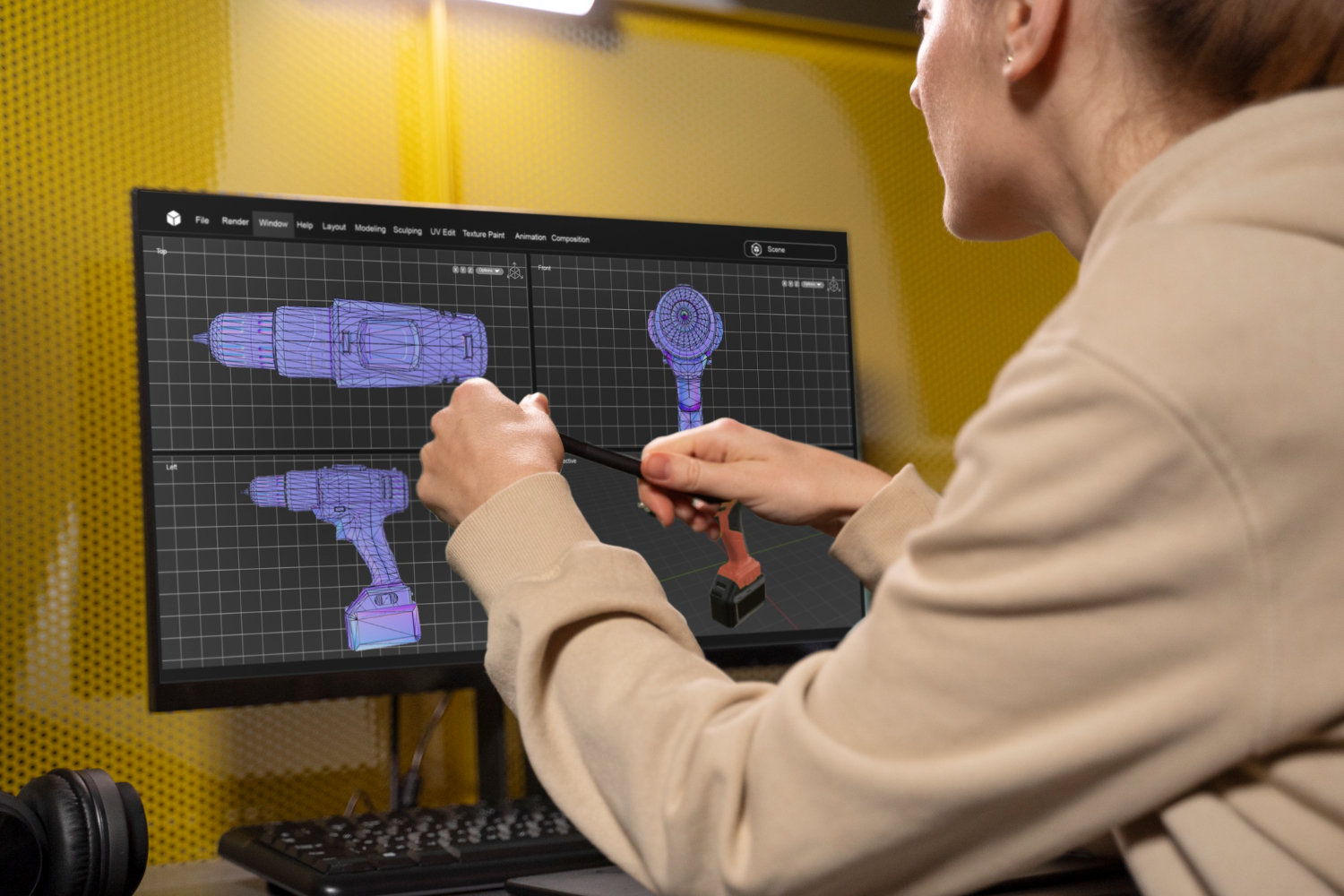
A smart product development workflow uses different 3D printing technologies at different stages. Here's how to think about it:
Concept stage — use FDM. You're checking overall size, shape, and proportions. You're holding the enclosure in your hand to feel if it's the right size. FDM is fast, cheap, and good enough for this. Don't waste time perfecting details at this stage.
Design validation — use SLA. You're checking precise fit of internal components, testing button feel and display alignment, and evaluating the visual design. SLA's smooth surface and tight tolerances give you an accurate preview of the final product.
Functional testing — use SLS or MJF. You're testing durability, snap-fit performance, drop resistance, and thermal behavior. SLS nylon is tough and produces parts that behave much closer to injection-molded plastic than FDM or SLA parts.
Pre-production and small batch — use SLS or MJF. If you need 20–200 units for beta testing, a pilot launch, or early sales, SLS and MJF can produce them without mold investment.
A 3D print service like 3D On Demand lets you switch between these technologies seamlessly within a single order. Upload the same STEP file, select a different technology and material, and compare the results.
Post-Processing for a Professional Finish
Raw 3D prints rarely look like finished products. Post-processing bridges that gap.
Sanding and smoothing removes layer lines (FDM) or powder texture (SLS). Start with 120-grit and work up to 400-grit for a smooth finish. For SLA parts, light sanding with fine grit is usually sufficient.
Vapor smoothing (available for SLS nylon) creates a sealed, glossy surface by briefly exposing the part to a chemical vapor. This is great for enclosures that need to look polished without painting.
Dyeing works on SLS and MJF parts and penetrates the surface for a uniform color that doesn't chip or peel. Black is the most common, but other colors are available.
Painting and coating can make any 3D printed enclosure look like an injection-molded product. Apply a filler primer, sand smooth, and spray paint. For a truly professional result, add a clear coat.
Insert installation — heat-set threaded brass inserts for screw mounting, rubber feet or gaskets, and label or screen-print areas for branding.
Common Mistakes to Avoid
Designing for injection molding, not 3D printing. Draft angles, uniform wall thickness, and mold flow considerations don't apply to 3D printing. You have more geometric freedom — use it. But also respect the constraints: avoid large unsupported overhangs in FDM, and don't design features thinner than the minimum wall thickness.
Ignoring print orientation. How your enclosure is oriented on the print bed affects surface quality, strength, and support material placement. A good 3D printing service will optimize orientation for you — but it helps to design with orientation in mind. Keep critical surfaces (display windows, button openings) on the top or sides rather than the bottom.
Over-engineering the first prototype. Your first print should answer one question: does the general form factor work? Don't add snap-fits, ventilation patterns, and cable routing to version one. Keep it simple, test it, and layer in complexity over subsequent iterations.
Forgetting about assembly. Design your enclosure so that components can actually be installed. Consider the assembly sequence — which part goes in first? Can you reach the screws? Is there enough room for your fingers or tools?
What to Do Next
Ready to print your first enclosure? Here's the fastest path:
Design your enclosure around your internal components with the wall thicknesses and tolerances described above. Export as a STEP file for the best results — STEP preserves exact geometry, while STL approximates curved surfaces with triangles.
Upload your file to the 3D On Demand platform for an instant quote. Choose FDM if you're in the concept stage, SLA for visual prototypes, or SLS for functional testing. Select express production if you need parts within 24–48 hours.
When your enclosure arrives, test it with your actual electronics inside. Note what works and what doesn't. Adjust your CAD file and order the next iteration. With a 3D print on demand workflow, you can go through three or four design cycles in the time it would take to get a single CNC-machined prototype.
That's the power of on-demand 3D printing for electronics enclosure development: rapid iteration, zero tooling, and total design freedom at every stage.
Apr 8, 2026
Design during the day, print overnight, test the next morning. A practical workflow for running rapid prototyping iterations at one per day.
Apr 8, 2026
A structured checklist for testing 3D printed prototypes: visual inspection, fit testing, functional validation, and user testing. Get the most out of every iteration.
.webp)


Copyright © 3D On Demand